This is the seventh article in the Systrace series, primarily introducing the Vsync mechanism in Android. This article examines the display of each frame in the Android system from the perspective of Systrace. Vsync is a critical mechanism in Systrace. Although invisible and intangible when operating a phone, we can see in Systrace how the Android system, guided by Vsync signals, orderly performs rendering and composition for each frame, ensuring stable frame rates.
The purpose of this series is to view the overall operation of the Android system from a different perspective using Systrace, while also providing an alternative angle for learning the Framework. Perhaps you’ve read many articles about the Framework but can never remember the code, or you’re unclear about the execution flow. Maybe from Systrace’s graphical perspective, you can gain a deeper understanding.
Table of Contents
- Series Article Index
- Main Content
- Android Graphics Data Flow
- Graphic Data Flow in Systrace
- Vsync Offset
- HW_Vsync
- Other Addresses for This Article
- References
- About Me && Blog
Series Article Index
- Introduction to Systrace
- Systrace Basics - Prerequisites for Systrace
- Systrace Basics - Why 60 fps?
- Android Systrace Basics - SystemServer Explained
- Systrace Basics - SurfaceFlinger Explained
- Systrace Basics - Input Explained
- Systrace Basics - Vsync Explained
- Systrace Basics - Vsync-App: Detailed Explanation of Choreographer-Based Rendering Mechanism
- Systrace Basics - MainThread and RenderThread Explained
- Systrace Basics - Binder and Lock Contention Explained
- Systrace Basics - Triple Buffer Explained
- Systrace Basics - CPU Info Explained
- Systrace Smoothness in Action 1: Understanding Jank Principles
- Systrace Smoothness in Action 2: Case Analysis - MIUI Launcher Scroll Jank Analysis
- Systrace Smoothness in Action 3: FAQs During Jank Analysis
- Systrace Responsiveness in Action 1: Understanding Responsiveness Principles
- Systrace Responsiveness in Action 2: Responsiveness Analysis - Using App Startup as an Example
- Systrace Responsiveness in Action 3: Extended Knowledge on Responsiveness
- Systrace Thread CPU State Analysis Tips - Runnable
- Systrace Thread CPU State Analysis Tips - Running
- Systrace Thread CPU State Analysis Tips - Sleep and Uninterruptible Sleep
Main Content
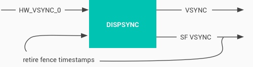
Vsync signals can be generated by hardware or simulated via software, though hardware generation is now standard. The Hardware Composer (HWC) produces VSYNC events and sends them to SurfaceFlinger via callbacks. DispSync then generates VSYNC_APP and VSYNC_SF signals from these for use by Choreographer and SurfaceFlinger.
In the article Detailed Explanation of Android Rendering Mechanism Based on Choreographer, we mentioned that Choreographer coordinates with Vsync to provide a stable Message processing timing for App-level rendering. When Vsync arrives, the system adjusts the signal period to control when each frame is drawn. Most current phones have a 60Hz refresh rate (16.6ms). To match this, the system sets the Vsync period to 16.6ms, waking Choreographer every period to perform app drawing—this is the primary purpose of Choreographer.
While Choreographer handles Vsync for the rendering layer (App), SurfaceFlinger handles it for the composition layer. SurfaceFlinger composites all prepared Surfaces when Vsync arrives.
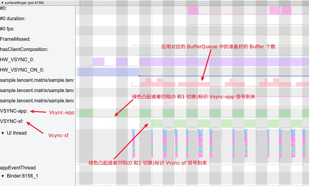
The diagram below shows VSYNC_APP and VSYNC_SF within the SurfaceFlinger process in Systrace.
Android Graphics Data Flow
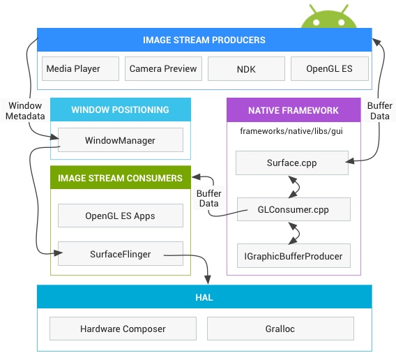
First, we must understand the high-level direction of graphics data. From app drawing to screen display, the process consists of several stages:
- Stage 1: Upon receiving
Vsync-App, the App performsmeasure,layout, anddraw(constructing aDisplayListcontaining OpenGL commands and data) on the main thread. This corresponds to the doFrame operation in Systrace’s main thread. - Stage 2: The CPU uploads data (via sharing or copying) to the GPU. On ARM devices, CPU and GPU usually share memory. This corresponds to the flush drawing commands operation in Systrace’s rendering thread.
- Stage 3: Notify the GPU to render. Real devices typically don’t block waiting for GPU completion; the CPU returns to other tasks immediately. The Fence mechanism is used for synchronization.
- Stage 4:
swapBuffersand notification toSurfaceFlingerfor layer composition. This corresponds to the eglSwapBuffersWithDamageKHR operation in Systrace’s rendering thread. - Stage 5:
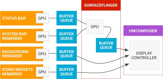
SurfaceFlingerstarts composition. If previous GPU tasks aren’t finished, it waits (Fence mechanism). Composition still relies on the GPU, but as a subsequent task. This corresponds toonMessageReceived(includinghandleTransaction,handleMessageInvalidate,handleMessageRefresh) inSurfaceFlinger‘s main thread.SurfaceFlingerdelegates some work to the Hardware Composer to offload the GPU; only layers HWC can’t handle (or those explicitly assigned to OpenGL) use OpenGL. - Stage 6: Final composited data is placed in the Frame Buffer and becomes visible upon refresh.
The following official diagram shows how frame data flows across processes from left to right:
Graphic Data Flow in Systrace
By mapping the abstract data flow above to Systrace, we get this:
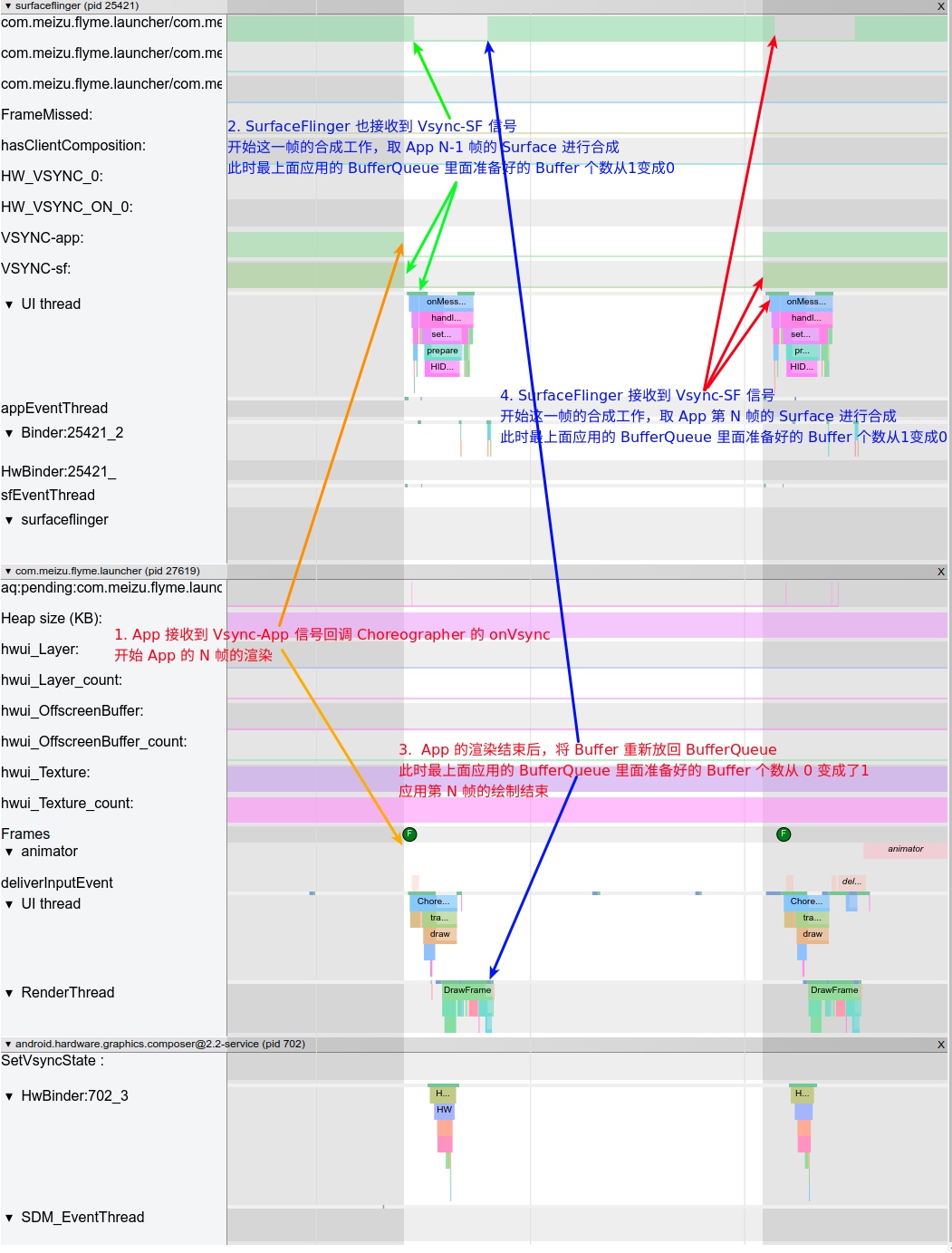
The diagram above includes SurfaceFlinger, App, and hwc processes. Let’s follow the numbers:
- First Vsync signal arrives;
SurfaceFlingerand App receive it simultaneously. SurfaceFlingerreceivesVsync-sfand begins compositing the App’s previous frame buffer.- App receives
Vsync-appand begins rendering the current frame buffer (stages 1-4 above). - Second Vsync signal arrives.
SurfaceFlingerretrieves the buffer the App rendered in step 2 and begins composition (stage 5). Simultaneously, the App receivesVsync-appand starts rendering the next frame buffer (stages 1-4).
Vsync Offset
As mentioned, HWC produces hardware Vsync, which DispSync converts into VSYNC_APP and VSYNC_SF.
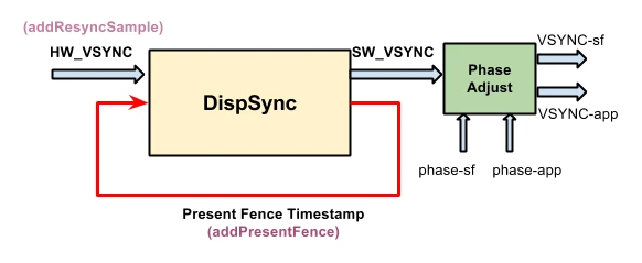
Both app and sf signals have offsets relative to hw_vsync_0, namely phase-app and phase-sf:

Vsync Offset refers to the difference between VSYNC_APP and VSYNC_SF (i.e., phase-sf - phase-app), which manufacturers can configure. If the offset is non-zero, the App and SurfaceFlinger don’t receive the signal simultaneously; they receive it separated by the Offset (usually 0-16.6ms).
Most manufacturers leave this at 0, so App and SurfaceFlinger receive signals simultaneously.
Check the values using Dumpsys SurfaceFlinger:
Offset = 0: (sf phase - app phase = 0)
1 | Sync configuration: |
Offset ≠ 0 (SF phase - app phase = 4 ms)
1 | Sync configuration: |
Now let’s see how Offset looks in Systrace.
Offset = 0
When Offset is 0, App and SurfaceFlinger receive Vsync simultaneously:
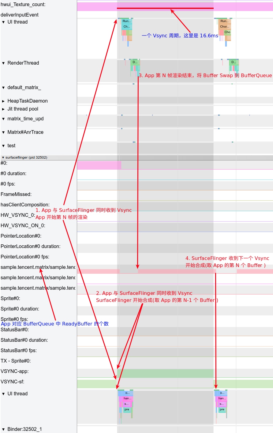
As shown, the App-rendered buffer must wait until the next Vsync-SF for composition, causing a ~16.6ms delay. You might wonder: if SurfaceFlinger could start composition immediately after the App swaps the buffer into BufferQueue, could we save those 0-16.6ms?
Yes, that’s exactly what the Offset mechanism does. The App receives Vsync first, performs rendering, and after the Offset delay, SurfaceFlinger receives Vsync and begins composition. If the app’s buffer is ready, SurfaceFlinger can include it in the current composition, allowing the user to see it sooner.
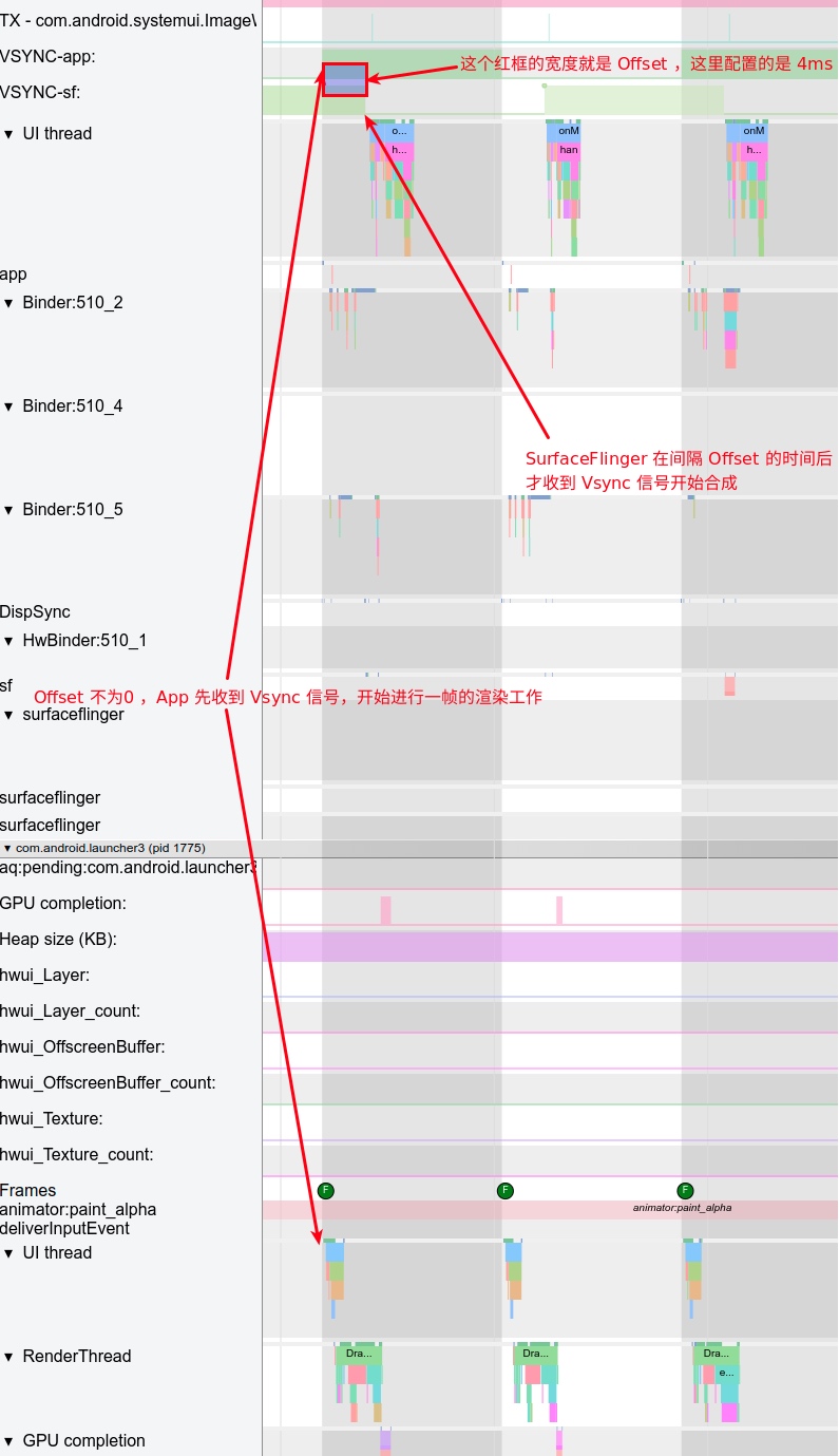
Offset ≠ 0
Below is an example with a 4ms Offset: SurfaceFlinger receives Vsync 4ms after the App does.
Pros and Cons of Offset
The challenge is determining the optimal Offset—one reason many manufacturers don’t configure it. Its effectiveness depends on device performance and usage scenarios.
- If Offset is too short: The app might not finish rendering before
SurfaceFlingerstarts composition. If no previous buffers are ready,SurfaceFlinger‘s current composition won’t include the new frame, delaying it until the nextVsync-SF. The delay effectively becomesVsync period + Offsetinstead of the expectedOffset. - If Offset is too long: It loses its purpose.
HW_Vsync
Note that hardware Vsync isn’t requested every time. It’s only requested from HWC if the last composition was more than 500ms ago.
Using Launcher scrolling as an example, you can see the HW_VSYNC state in the SurfaceFlinger process trace.
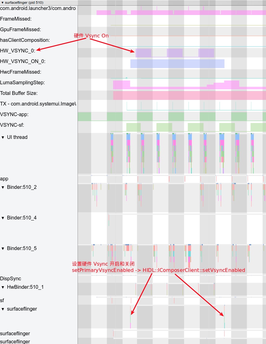
Subsequent Vsync requests from Apps can occur either with or without HW_VSYNC.
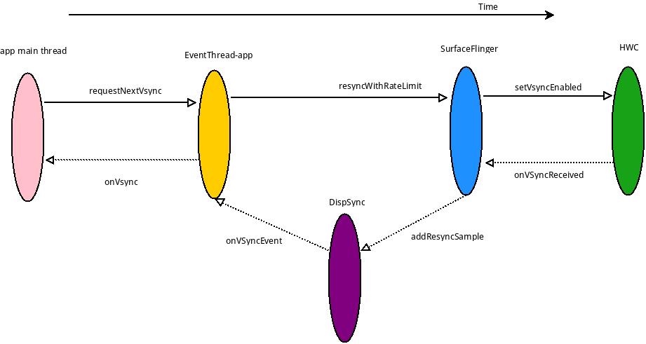
Without HW_VSYNC
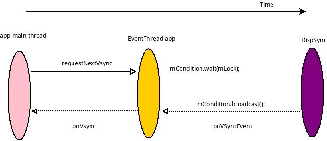
With HW_VSYNC
HW_VSYNC primarily uses recent hardware Vsync timestamps for prediction (usually 3-32, minimum 6). DispSync calculates SW_VSYNC after receiving 6 timestamps. As long as incoming Present Fence errors remain within threshold, hardware Vsync is turned off; otherwise it remains active to recalibrate SW_VSYNC. For details, see Generation and Transmission of SW-VSYNC. Here is their conclusion:
SurfaceFlingerimplements theHWC2::ComposerCallbackinterface to receive hardware VSYNC callbacks and pass them toDispSync.DispSyncrecords these timestamps. After collecting enough (currently ≥6), it calculates theSW-VSYNCoffsetmPeriod. This is used byDispSyncThreadto periodically wake and notify listeners—SurfaceFlingerand all apps needing to render. Listeners register viaConnectionobjects inEventThread, which is linked toDispSyncThreadthroughDispSyncSource. WhenSW-VSYNCarrives,EventThreadnotifies connections, triggeringSurfaceFlingercomposition and App frame drawing. Once enough hardware VSYNCs are received and errors are within tolerance, hardware VSYNC is disabled viaEventControlThread.
Other Addresses for This Article
To be updated.
References
- VSYNC
- Sync and Vsync
- Android Graphics Architecture
- Generation and Transmission of SW-VSYNC
- DispSync Implementation Details
About Me && Blog
Below is my personal intro and related links. I look forward to exchanging ideas with fellow professionals. “When three walk together, one can always be my teacher!”
- Blogger Intro: Includes personal WeChat and WeChat group links.
- Blog Content Navigation: A guide for my blog content.
- Curated Excellent Blog Articles - Android Performance Optimization Must-Knows: Welcome to recommend projects/articles.
- Android Performance Optimization Knowledge Planet: Welcome to join and thank you for your support~
One walks faster alone, but a group walks further together.